English
 Spanish
 French
 Arabic
Electric Pole Accessories
- Home
- Products
- Anchoring Clamp
- CW-PA70 Plastic Tension Clamp with Bail Retaining Clip
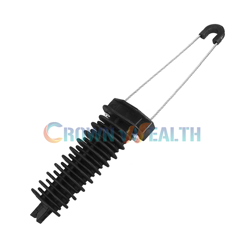
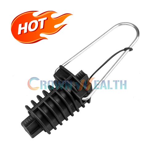
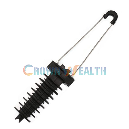
The CW-PA70 plastic tension clamp is an overhead cable anchoring component with an insulating body and a dedicated bail retaining clip. Use the conductor cross-section, messenger diameter and breaking load together when reviewing this model for your project.
| Specification | CW-PA70 |
|---|---|
| Product type | Plastic tension clamp |
| Conductor cross-section | 70–95 mm² |
| Messenger diameter | 12.8–14.8 mm |
| Breaking load | 8 kN |
| Body material | Mechanically strong, weather-resistant insulating material |
| Bail retention | Clip designed to prevent the bail from slipping out of the body |
| Standard reference | NFC33-042 |
Size selection: 70–95 mm² describes conductor cross-section, while 12.8–14.8 mm describes messenger diameter. These are different measurements. Check the cable construction and the outside diameter of the member being gripped against your cable drawing.
Load selection: 8 kN is the breaking-load specification. It is not the allowable working load or installation tension for your cable assembly.
The CW-PA70 specification covers a larger listed conductor and messenger range than CW-PA50. This gives you a distinct option to evaluate when the cable dimensions fall outside the PA50 range. Final selection still depends on the complete cable construction and attachment arrangement.
The specially designed clip helps prevent the bail from slipping out of the clamp body. Its purpose is retention at the bail-to-body connection. Include clip condition and engagement in your inspection of the completed assembly.
The clamp body uses insulating material specified for high mechanical strength and weather resistance. Assess the body construction together with cable fit and the required mechanical performance. An insulating body alone does not establish a voltage rating for the complete assembly.
The stated breaking load supports technical comparison between models. Your project designer must separately establish the permitted service load and design margin, taking the cable, support fitting and anchorage into account.
Consider CW-PA70 for compatible overhead cable anchoring arrangements within its listed dimensional ranges. Confirm the cable’s load-bearing member and the support connection before approval for a particular installation.
| Model | Conductor cross-section | Messenger diameter | Breaking load |
|---|---|---|---|
| CW-PA70 | 70–95 mm² | 12.8–14.8 mm | 8 kN |
| CW-PA50 plastic tension clamp | 50–70 mm² | 11.2–12.8 mm | 6 kN |
The ranges share boundary values, but the models should not be treated as interchangeable. For a 70 mm² conductor or 12.8 mm messenger, review both dimensions, cable construction and load requirements before choosing a model. A higher breaking load alone does not make a clamp suitable for a smaller cable.
Obtain the fitting instructions for your exact clamp, cable and support assembly before installation. Use this checklist to prepare the necessary compatibility and inspection checks:
Torque, span length, installation tension and tool requirements are not specified here. Confirm them for the complete installation; do not use the 8 kN breaking load as the tensioning target.

Hbcrownwealth is a manufacturer, supplier and wholesaler of overhead hardware for power and telecommunications systems. Send your CW-PA70 requirements with the cable and attachment drawings so the quotation can identify the proposed configuration clearly.
For technical approval, specify the material information, dimensional checks, mechanical test documents and standard edition your project requires. Confirm document availability and the agreed inspection criteria before placing your order.
For an OEM/ODM inquiry, provide drawings and explain the changes you need for feasibility review. Available customization, samples, minimum order quantity and production lead time must be confirmed for the order. For repeat supply, reference the approved configuration as well as the model number.
The specified ranges are 70–95 mm² conductor cross-section and 12.8–14.8 mm messenger diameter. Check both against your cable drawing, including insulation and the member being gripped.
CW-PA70 lists 70–95 mm², 12.8–14.8 mm and an 8 kN breaking load. CW-PA50 lists 50–70 mm², 11.2–12.8 mm and 6 kN. Select by fit and the complete mechanical requirements rather than the model number alone.
Choose only after reviewing both cable dimensions and the project load requirements. A 70 mm² conductor or 12.8 mm messenger sits at a listed boundary, but that single measurement does not establish interchangeability. Send your cable drawing for review.
The clip is designed to prevent the bail from slipping out of the body. Correct clip engagement must be checked alongside cable seating and the support connection under the applicable installation instructions.
No. The specified 8 kN is the breaking load. Allowable working load, installation tension and the applicable design margin must be established separately for your cable and anchorage assembly.
The body is described as mechanically strong, weather-resistant insulating material. The published information does not identify the bail material, a specific polymer grade, UV rating or operating temperature range. Request confirmation of any project-specific material or exposure requirements.
NFC33-042 is listed as a standard reference; it is not by itself proof of certification. Specify the required edition and certificate or test-report scope so the available documentation can be checked.
Provide CW-PA70, quantity, conductor cross-section, messenger diameter, cable construction and attachment details. Include the environment, required mechanical performance and documents. For custom supply, add drawings and the proposed changes for feasibility review.
Use the inquiry form below to send Hbcrownwealth your cable datasheet, support-fitting drawing and order quantity. Identify any required documents or acceptance tests so they can be addressed in the quotation.
| Specification | CW-PA70 |
|---|---|
| Product type | Plastic tension clamp |
| Conductor cross-section | 70–95 mm² |
| Messenger diameter | 12.8–14.8 mm |
| Breaking load | 8 kN |
| Body material | Mechanically strong, weather-resistant insulating material |
| Bail retention | Clip designed to prevent the bail from slipping out of the body |
| Standard reference | NFC33-042 |
Conductor cross-section is measured in mm²; messenger diameter is measured in mm. Check both against the cable construction and the member being gripped.
Breaking load is not the allowable working load or installation tension. Confirm the required NFC33-042 edition and supporting documents for your order.
The CW-PA70 plastic tension clamp is an overhead cable anchoring component with an insulating body and a dedicated bail retaining clip. Use the conductor cross-section, messenger diameter and breaking load together when reviewing this model for your project.
| Specification | CW-PA70 |
|---|---|
| Product type | Plastic tension clamp |
| Conductor cross-section | 70–95 mm² |
| Messenger diameter | 12.8–14.8 mm |
| Breaking load | 8 kN |
| Body material | Mechanically strong, weather-resistant insulating material |
| Bail retention | Clip designed to prevent the bail from slipping out of the body |
| Standard reference | NFC33-042 |
Size selection: 70–95 mm² describes conductor cross-section, while 12.8–14.8 mm describes messenger diameter. These are different measurements. Check the cable construction and the outside diameter of the member being gripped against your cable drawing.
Load selection: 8 kN is the breaking-load specification. It is not the allowable working load or installation tension for your cable assembly.
The CW-PA70 specification covers a larger listed conductor and messenger range than CW-PA50. This gives you a distinct option to evaluate when the cable dimensions fall outside the PA50 range. Final selection still depends on the complete cable construction and attachment arrangement.
The specially designed clip helps prevent the bail from slipping out of the clamp body. Its purpose is retention at the bail-to-body connection. Include clip condition and engagement in your inspection of the completed assembly.
The clamp body uses insulating material specified for high mechanical strength and weather resistance. Assess the body construction together with cable fit and the required mechanical performance. An insulating body alone does not establish a voltage rating for the complete assembly.
The stated breaking load supports technical comparison between models. Your project designer must separately establish the permitted service load and design margin, taking the cable, support fitting and anchorage into account.
Consider CW-PA70 for compatible overhead cable anchoring arrangements within its listed dimensional ranges. Confirm the cable’s load-bearing member and the support connection before approval for a particular installation.
| Model | Conductor cross-section | Messenger diameter | Breaking load |
|---|---|---|---|
| CW-PA70 | 70–95 mm² | 12.8–14.8 mm | 8 kN |
| CW-PA50 plastic tension clamp | 50–70 mm² | 11.2–12.8 mm | 6 kN |
The ranges share boundary values, but the models should not be treated as interchangeable. For a 70 mm² conductor or 12.8 mm messenger, review both dimensions, cable construction and load requirements before choosing a model. A higher breaking load alone does not make a clamp suitable for a smaller cable.
Obtain the fitting instructions for your exact clamp, cable and support assembly before installation. Use this checklist to prepare the necessary compatibility and inspection checks:
Torque, span length, installation tension and tool requirements are not specified here. Confirm them for the complete installation; do not use the 8 kN breaking load as the tensioning target.
Hbcrownwealth is a manufacturer, supplier and wholesaler of overhead hardware for power and telecommunications systems. Send your CW-PA70 requirements with the cable and attachment drawings so the quotation can identify the proposed configuration clearly.
For technical approval, specify the material information, dimensional checks, mechanical test documents and standard edition your project requires. Confirm document availability and the agreed inspection criteria before placing your order.
For an OEM/ODM inquiry, provide drawings and explain the changes you need for feasibility review. Available customization, samples, minimum order quantity and production lead time must be confirmed for the order. For repeat supply, reference the approved configuration as well as the model number.
The specified ranges are 70–95 mm² conductor cross-section and 12.8–14.8 mm messenger diameter. Check both against your cable drawing, including insulation and the member being gripped.
CW-PA70 lists 70–95 mm², 12.8–14.8 mm and an 8 kN breaking load. CW-PA50 lists 50–70 mm², 11.2–12.8 mm and 6 kN. Select by fit and the complete mechanical requirements rather than the model number alone.
Choose only after reviewing both cable dimensions and the project load requirements. A 70 mm² conductor or 12.8 mm messenger sits at a listed boundary, but that single measurement does not establish interchangeability. Send your cable drawing for review.
The clip is designed to prevent the bail from slipping out of the body. Correct clip engagement must be checked alongside cable seating and the support connection under the applicable installation instructions.
No. The specified 8 kN is the breaking load. Allowable working load, installation tension and the applicable design margin must be established separately for your cable and anchorage assembly.
The body is described as mechanically strong, weather-resistant insulating material. The published information does not identify the bail material, a specific polymer grade, UV rating or operating temperature range. Request confirmation of any project-specific material or exposure requirements.
NFC33-042 is listed as a standard reference; it is not by itself proof of certification. Specify the required edition and certificate or test-report scope so the available documentation can be checked.
Provide CW-PA70, quantity, conductor cross-section, messenger diameter, cable construction and attachment details. Include the environment, required mechanical performance and documents. For custom supply, add drawings and the proposed changes for feasibility review.
Use the inquiry form below to send Hbcrownwealth your cable datasheet, support-fitting drawing and order quantity. Identify any required documents or acceptance tests so they can be addressed in the quotation.
| Specification | CW-PA70 |
|---|---|
| Product type | Plastic tension clamp |
| Conductor cross-section | 70–95 mm² |
| Messenger diameter | 12.8–14.8 mm |
| Breaking load | 8 kN |
| Body material | Mechanically strong, weather-resistant insulating material |
| Bail retention | Clip designed to prevent the bail from slipping out of the body |
| Standard reference | NFC33-042 |
Conductor cross-section is measured in mm²; messenger diameter is measured in mm. Check both against the cable construction and the member being gripped.
Breaking load is not the allowable working load or installation tension. Confirm the required NFC33-042 edition and supporting documents for your order.